The Apple Lossy compression format was introduced in the A15 and M2 chipsets (which share the same GPU generation) and it enables sampling and rendering to textures with a 1:2 compression ratio. The format is transparent to the application: the GPU handles compression and decompression automatically, and the block layout is never exposed through the API.
A few weeks ago I wrote about it in Hardware Image Compression and gave a brief overview of how it’s enabled at the API level and how the results compare to other hardware compression implementations. In this blog post I’ll take a deeper look at the underlying block format and how the hardware decoder is implemented.
Unlike traditional GPU compression formats, the lossy format is not documented. There’s no spec that you can read to understand how the format works. In order to do that I employed the same technique I described in Writing to Compressed Textures in Metal.
Metal heaps provide a useful tool to inspect how textures are laid out in memory. Raw compressed bytes can be read by creating a placement MTLHeap and placing both a lossy MTLTexture and an MTLBuffer at offset 0, so they alias the same memory. After blitting data into the lossy texture, the raw compressed bytes can be read from the aliased buffer. The reverse also works: writing raw bytes into the buffer and then reading the aliased texture gives GPU-decompressed pixels.
This provides a powerful tool to reverse engineer the format. We can upload simple textures and read back the compressed bits to try to understand how the format works. I started with single channel images (R8 format), first with flat colors, then smooth gradients, simple patterns, random noise, etc. Once I noticed a pattern in the block that would explain the behavior of the output, I would poke at the bits in the block to validate the theory.
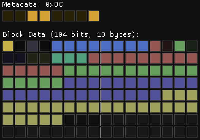
Following this procedure I quickly discovered some basic facts about the format. The image is broken up into 8×4 blocks and the size of each block is 128 bits. Each block has 1 byte of metadata allocated after the block data.
Studying the encoded output for different images it became clear the format supports multiple modes. In some modes there is a base color and per-pixel deltas are applied to it. In others the block is divided into four 4×2 quadrants with a base color for each one. In others the base color is a gradient, similar to ETC2 planar mode, but with deltas applied to it.
I discovered all these features by just poking at an 8×4 image using the tool pictured above. When I thought I had most of the details of the format figured out, I tried to decode entire pictures, but to my surprise the results were all wrong. I was clearly missing something.
It turned out that blocks aren’t strictly 128 bits. Blocks can use fewer bytes, and they are packed sequentially within a tile. I was assuming blocks were at fixed 16-byte strides to support random access, so I was sampling uninitialized data or bits corresponding to a different block.
Memory Layout
While Apple advertises that lossy formats provide 1:2 compression, the memory use is actually a little higher, because there’s one additional byte of metadata allocated for every 8×4 block (32 pixels). Each of these bytes describes the format of its corresponding block.
A compressed texture is laid out in two sections: first the block data, followed by the per-block metadata:
Within the data section, blocks are grouped into tiles of 2×4 blocks (16×16 pixels, 8 blocks per tile). Each tile is 128 bytes, exactly one cache line, and the 8 blocks inside it are packed sequentially in Y-first Morton order.
Here’s the interesting part: the blocks inside a tile are not all the same size. A flat block might use just 1 byte while a complex block takes the full 16. So how do you find block N within a tile without parsing the whole stream? One of the most important properties of a hardware texture format is random access, and walking a variable-length stream to find a block would defeat that.
The answer lies in the metadata. The size of each block is fully determined by its metadata byte, so locating a block is a two-step process: load the 16 metadata bytes for the tile, then compute a prefix sum of the block sizes to get the offset. The metadata doubles as an index.
Above the tile level, blocks are grouped into macro-tiles of 128×128 pixels (8×8 tiles, or 512 blocks). I covered the motivation for this structure in The True Size of ASTC Textures: aligning texture dimensions to the block grid would normally round up to the next power of two, which wastes a lot of memory. Macro-tiles let the texture round up to the macro-tile boundary instead, which is a much finer granularity. Macro-tiles are arranged in row-major order, and tiles within a macro-tile are in Y-first Morton order.
The metadata section doesn’t follow this hierarchy. It uses a single Y-first Morton ordering over the entire block grid, with no macro-tile grouping. It was a bit surprising to discover that the metadata didn’t match the data layout, but since the metadata is much smaller, the waste from power-of-two alignment is less objectionable.
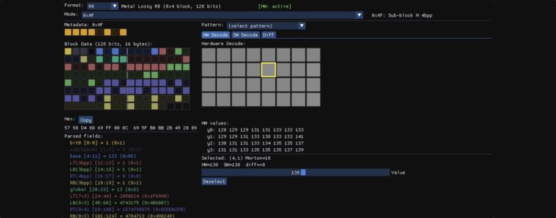
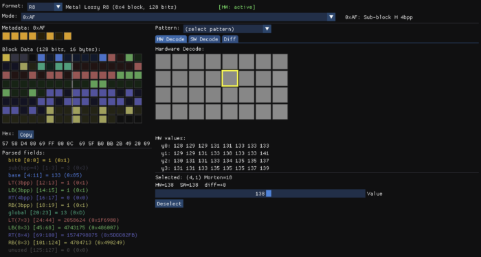
Here’s a brief description of all the block types I identified in the R8 Lossy format with their corresponding meta data:
| Mode | Meta | Description |
|---|---|---|
| 0 | 0x05, 0x09, 0x0D | Flat deltas (1/2/3 bpp) |
| 1 | 0x25, 0x29, 0x2D | Masked deltas (1/2/3 bpp) |
| 2 | 0x46, 0x4A, 0x4E | Gradient + deltas (1/2/3 bpp) |
| 3 | 0x60, 0x61 | Constant block |
| 4 | 0x82..0x8F | Flat deltas with per-quadrant bit allocation |
| 5 | 0xA2..0xAF | Masked deltas with per-quadrant bit allocation |
| 6 | 0xC3..0xCF | Gradient + deltas with per-quadrant bit allocation |
| 7 | 0xF0..0xFF | Quantized with per-quadrant sub-mode selection |
As shown in the table, the mode family is determined by the upper 3 bits. The block size is determined as follows: Mode 7 blocks are always 128 bits (16 bytes), for all other modes, the block size is 8 * ((meta & 0x1F) + 1) bits.
Now that we have a high level overview, let’s take a closer view of the block format.
R8 Lossy Format
With the exception of the blocks with meta data 0x60 and 0xF0..0xFF, all other blocks share a common header:
bits[0]    = has_global
bits[1:3]  = bpp - 1
bits[4:11] = 8-bit base color
bits[12+]  = mode-specific payload
When the common header is present, these fields always have the same meaning: a flag indicating whether a global offset is applied to the deltas, the number of bits per delta (bpp), and the 8-bit base color that the deltas are applied to.
Mode 3 – Constant
The simplest block is a flat block with a single color. There are two variants of this mode with meta data 0x60 and 0x61. Blocks with meta 0x61 use the common header layout and provide an 8-bit base color in bits[4:11], but the has_global flag and bpp fields are unused and must be 0. This results in a block size of 2 bytes. Blocks with meta 0x60 are more compact. The base color is provided in bits[0:7] so that the entire block only uses 1 byte.
Mode 0 – Per-Pixel Deltas
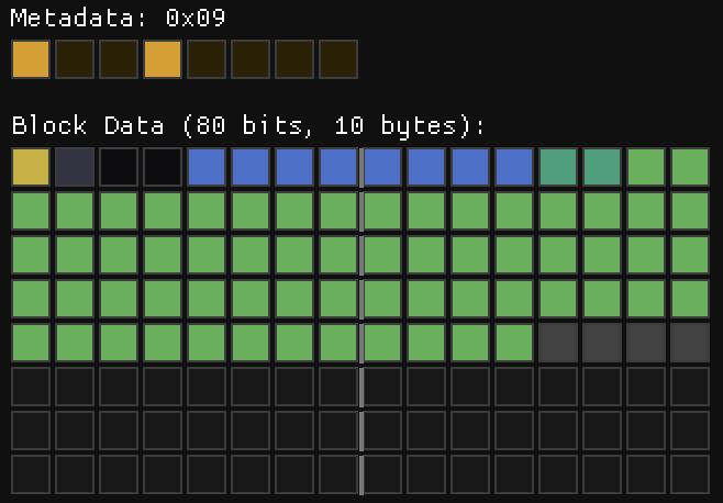
This is when things start to get interesting. When you have a nearly flat block, with small variations, you can represent that block exactly with a base color and small deltas. This is what this block does. The base color is provided in the common header and bits[1:3] specify the number of bits allocated for each per pixel delta. This leads to 3 variants of this block format depending on the total size, each one with a different metadata:
0x05: 1 bpp (48 bits – 6 Bytes).0x09: 2 bpp (80 bits – 10 Bytes).0x0D: 3 bpp (112 bits – 14 Bytes).
Only 31 deltas are provided, the first pixel of the block is the anchor and it always takes the value of the base color. When the has_global flag is set, there’s an additional entry before the deltas that acts as a global offset subtracted from the per-pixel deltas. To make things more interesting, the deltas are stored in Y-first Morton order. Both deltas and offset are signed values stored in two’s complement, so when only one bit is present the values are either -1 or 0.
The final pixel color is given by the following formula:
color = (base + delta - global_offset) & 0xFF
Note that the colors overflow, they wrap around instead of clamping to 0 or 255. This is the case in all modes unless noted otherwise.
While this mode sort of makes sense, some of the decisions still baffle me. Why is there a global offset when you can just modify the base color? Why 31 deltas instead of 32? My guess is that the encoder simply reads the first pixel and then compares the remaining pixels against it instead of making an effort to find the optimal base color that could represent a wider range. Would that have been much more expensive?
Mode 1 – Bit-Mask Deltas
This mode is just like mode 0, but the deltas do not affect the corresponding Y-first Morton pixel. Instead, each delta affects a group of up to 8 pixels. The mask values in raster order are as follows:
static const uint32_t kDeltaMaskRaster[31] = {
                0x00000003, 0x00000100, 0x00000300,
    0x00000007, 0x00000008, 0x00000700, 0x00000001,
    0x00010000, 0x00030000, 0x01000000, 0x03000000,
    0x07070000, 0x08080000, 0x04000000, 0x08000000,
    0x000000f0, 0x000000e0, 0x0000f000, 0x0000e000,
    0x000000c0, 0x00000080, 0x0000c000, 0x00008000,
    0xf0f00000, 0x00e00000, 0x10000000, 0xe0000000,
    0x00c00000, 0x00800000, 0xc0000000, 0x80000000,
};
This is again quite puzzling. Deltas in one quadrant only affect pixels in the same quadrant. The masks in each quadrant are similar, but not exactly the same, and they lack any kind of symmetry or orthogonality, so it’s unclear to me what’s the best procedure to compute the optimal delta values for a given block.
Since individual pixels are affected by multiple deltas, the range of values that can be represented in this mode is higher than the range of a single delta, but it’s not possible to represent all values block within that range. My guess is that the hardware uses a heuristic to choose the deltas and ranks the resulting block against the other options.
Like Mode 0, this mode has the following variants:
0x25: 1 bpp (48 bits – 6 Bytes).0x29: 2 bpp (80 bits – 10 Bytes).0x2D: 3 bpp (112 bits – 14 Bytes).
Mode 2 – Gradient + Per-Pixel Deltas
One of the most useful blocks in the ETC2 format is the planar mode, but often the resulting gradients are too smooth. Our eyes are very sensitive to small variations in smooth regions, when the grain and or small details are missing, that stands out. Mode 2 solves that by combining smooth gradients with per pixel offsets.
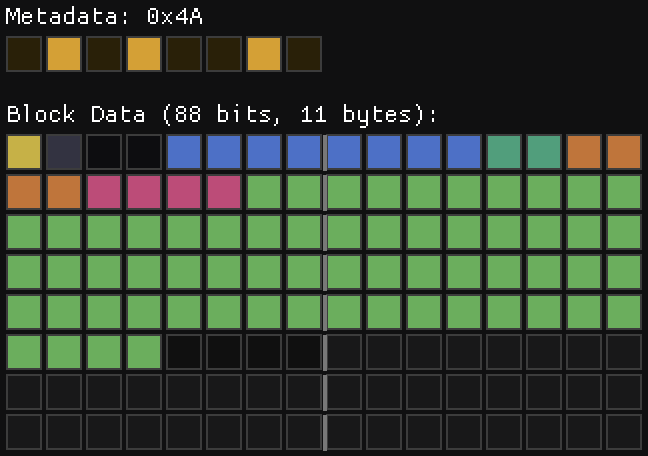
The slopes are stored in two 4 bit fields using two’s complement. The way the interpolated color is computed is straightforward:
for (int y = 0; y < 4; y++) {
    for (int x = 0; x < 8; x++) {
        pixels[y * 8 + x] = base + x_slope * x + y_slope * y;
    }
}
The deltas are then applied on top of that.
Like in previous modes, there are three variants, for 1, 2 and 3 bpp:
0x46: 1 bpp (7 Bytes)0x4A: 2 bpp (11 Bytes)0x4E: 3 bpp (15 Bytes)
Mode 4 – Flat deltas with per-quadrant bit allocation
This mode is similar to mode 0, but divided into 4 sub-blocks (LT, LB, RT, RB), each covering a 4×2 pixel region. The mode has the standard header, with the addition of 4 2-bit codes in bits[12:19]. These encode the bpp of each of the sub-blocks as follows: sub-block bpp = bpp - code. Sub-blocks with zero or negative bpp are skipped, meaning the all the base color without deltas.
The remaining bits provide the per-pixel deltas in y-first Morton order, which is also the sub-block order. Like in previous modes, the delta for the first pixel is skipped (LT has 7 deltas; LB, RT, RB have 8 each). If a global offset is present, it’s applied to the deltas of all sub-blocks.
The nibble of the meta-data depends on the size of the block, which is dependent on both, the first 4 header bits and the sub-block codes. These need to match exactly. If the block size is larger than the allocated size, or if it uses fewer bytes than the allocated size, then the block is considered invalid and the output is all 255.
Mode 5 – Masked deltas with per-quadrant bit allocation
This mode is like mode 1, but also using per-quadrant bit allocation. The bit layout is exactly the same as mode 4, but the deltas are applied using the same mask scheme of mode 1.
Mode 6 – Planar + deltas with per-quadrant bit allocation
This mode is just like mode 2, but using per-quadrant bit allocation. The bit layout is exactly the same as mode 4 and 5, but with the 2 slope fields prior to the per pixel deltas.
Putting it all together.
In practice, modes 0, 1, 2, 4, 5 & 6 are all one mode with certain bitfields and features turned on or off. After the standard header you just have the following optional fields:
if (mode == 4 || mode == 5 || mode == 6) {
    qbpp = read_bits(8);
}
if (has_global) {
    global = read_bits(bpp);
}
if (mode == 2 || mode == 6) {
    x_slope = read_bits(4);
    y_slope = read_bits(4);
}
All modes have a base color and deltas applied to it. In modes 2 and 6 the base color is modified by the slopes, while the remaining modes have a flat color. The modes with uniform deltas are just special cases of the modes with per-quadrant deltas. When all deltas have the same bpp, the encoder picks the uniform-delta mode family (0, 1, or 2) which omits the per-quadrant field entirely.
Mode 7 – Quantized with per-quadrant mode selection
In this mode the standard header is not present, instead the layout is determined by the meta data bits. Like the previous modes, this one also divides the block in 4 quadrants. The format of each of these quadrants is determined by the lower 4 bits of the meta data in the usual Y-first Morton order (0->LT, 1->LB, 2->RT, 3->RB). When the corresponding bit is 1, the sub-block is stored using absolute values with 4-bit quantization, otherwise it uses a more complex sub-block delta format.
The quantized mode is straightforward: 8 pixels × 4 bits = 32 bits per quadrant, but the 4-bit dequantization is a bit unusual. The most common approach is to replicate the top bits so that the extremes are represented exactly: (n << 4) | n, that is, 0 maps to 0 and 0xF (15) maps to 0xFF (255). However, the lossy format achieves that by handling the extremes as special cases and then using a nearly uniform quantization interval.
inline uint8_t lossy_dequantize(uint8_t n) {
    if (n == 0) return 0;
    if (n == 15) return 255;
    return (n << 4) | (n & 1 ? 7 : 8);
}
This results in the following possible values:
n:   0   1   2   3   4   5   6   7   8   9  10  11  12  13  14  15
q:   0  23  40  55  72  87 104 119 136 151 168 183 200 215 232 255
Why this choice? I have no idea. I would understand the use of uniform quantization intervals, since that makes quantization easier, and snapping the endpoints to the extremes makes sense, but the alternating 17-15 interval is a curious choice.
The sub-block delta format encodes 8 pixels (4×2 region) using a base value plus per-pixel deltas encoded in 32 bits. The first 3 bits encode a header that selects the step size and the way the deltas are applied. The following 5 bits provide the base color, and the remaining data is mode-dependent.
bits[0:2]   3-bit header
bits[3:7]   5-bit base color
bits[8:31]  24-bit per-pixel data
This provides 8 different modes, but with the exception of mode 0, all have the same structure: A base value, an anchor pixel selector, and 7 per-pixel deltas, but pack them differently into the remaining 24 bits:
Fine Step (bit2==0) | Large Steps (bit2==1) | |
|---|---|---|
| Bits per delta | 2 bits | 3 bits |
| Global offset | 3 bits | — |
| Base value | base5 | base5 * 8 + round |
| Step sizes | 1, 2, 4 | 4, 8, 16, 32 |
The fine step mode trades delta precision (2 bpp) for a 3-bit global offset (value × 32), giving coarse block-wide shifts. The large step mode uses those same bits for an extra delta bit per pixel (3 bpp) that combined with the larger step sizes allows addressing a larger range of values.
The anchor pixel selector uses 3 bits to specify the pixel that does not have deltas applied to it.
The dequantization procedure is also interesting. The anchor pixel is simply:
pixel[anchor] = base + global + roundwhere the round is mode-dependent and annoyingly not step/2. The non-anchor pixels are:
pixel[i] = base + global + delta * step + step/2;where step is mode dependent and delta is the per-pixel delta.
As in the absolute quantization mode, special attention is paid to reproduce the extremes exactly by snapping them to the endpoints. When the delta is 0 and the resulting pixel value is within step/2 of 0, it snaps to 0. When delta is 255 and the pixel value is within step/2 of 255, it snaps to 255. Additionally, unlike all the other modes, when values overflow the 8-bit range, the values do not wrap, but are clamped to 0 and 255.
Finally, when the 3-bit sub-block header is 0 the data encodes a constant or near-constant block using 1 bit per pixel offsets.
This description is not a full specification. I’ve glossed over some of the details in order to make the text more tolerable. I’d be happy to provide a reference decoder if anyone is interested.
Conclusions
It’s clear that some of the features of the format are designed not just to save memory, but to save bandwidth. When a tile has a flat color, the entire tile is represented in just 8 bytes, while more complex tiles can take up to 128 bytes.
I suspect the lossless format has a similar structure, but with a larger tile size to allow for blocks stored without compression or quantization while still providing bandwidth savings in common scenarios. My guess is that modes 0-6 behave the same way, with a limit of 256 bits instead of 128, and that mode 7 encodes a fully decompressed block instead of using quantization.
While I think I have a good understanding of the underlying format, I still have some open questions. Some of the choices in the format are puzzling and perhaps that’s a sign that I still don’t have a complete understanding. How would one write a fast, efficient encoder for this format?
Initially I thought the encoder would be implemented in software, in a way not too different to what I’ve done for Spark. Apple even has support for tile shaders, which seem particularly well suited for this task. However, my attempts to use tile shaders for this purpose haven’t produced satisfactory outcomes.
My conclusion is that the encoder is fully implemented in hardware. An encoder for this format should not require the use of floating point math, so the implementation could be fairly compact. A hardware encoder could target multiple modes in parallel and select the best match.
Beyond R8, I’ve also fully decoded the RG8 format. It follows the same principles and has many similarities, but it’s significantly more complex. Bit allocation for each of the two components is variable, and the sub-block delta format is convoluted enough that I had to rely on a 256-element table to map the header bits to all the possible bit allocations. I could not find a formula or pattern that worked for all cases. I find it unlikely that this is how the format was actually designed, so I hope I’m just missing something.
The RGBA8 format is likely to be even more intricate, and my effort to fully decode it is on pause. Partly because I’m losing steam, and partly because this work doesn’t have any immediate practical application. It’s been a fun and intriguing exercise, and I’ve learned a few things along the way, but whether any of this knowledge turns out to be useful elsewhere remains to be seen.